IEC 62121 pdf download
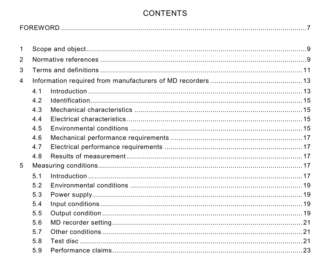
IEC 62121 pdf download.Methods of measurement for minidisc recorders/players
1 Scope and object
This International Standard specifies the measuring methods for recording and reproducing equipment for MiniDiscs that conform to the specifications of IEC 61 909. NOTE 1 For convenience, this recording and reproducing equipment will be referred to as “MD recorder” hereinafter. The reproducing part of this equipment or equipment with only a reproducing function will be referred to as “MD player” throughout the text of this standard. If there is no risk of misunderstanding, the term “MD recorder” will be generally used. NOTE 2 This standard does not include specifications for listening tests (see IEC 60268-1 3). The object of this standard is to list and define the characteristics affecting the performance of MiniDisc recorders or players, to establish conditions and methods of measurement of those characteristics, and to standardize the presentation of the results.
3 Terms and definitions
For the purpose of this International Standard, the terms and definitions given in the relevant clauses pertaining to measurement (see clauses 6 and 7) and the following definitions apply. 3.1 meaning of the expression “designated xxxxx” the item or value that is designated by a manufacturer based on the reference item or value EXAMPLE: Designated recording level: This is the recording level designated by a manufacturer based on the reference recording level which is indicated on an attached level meter 3.2 reference frequency the value is 1 kHz 3.3 reference recording level the reference for measurements and corresponds to the average music level It is equal to –1 2 dB of the full scale signal level of the MiniDisc (= 0,5 V)3.4 maximum recording level this level is specified as the maximum in the test disc. It is equal to the full scale signal level of the MiniDisc (= 2,0 V) 3.5 reference source impedance the impedance designated as the source impedance for the input terminal. An equivalent resistor should terminate the input terminal as the source impedance during the measurements 3.6 reference input level the input level of the reference frequency signal at the input terminal to attain the reference recording level at a designated attenuation of the recording volume control 3.7 reference load impedance the impedance designated as the load impedance for the output terminal. An equivalent resistor should terminate the output terminal as the load impedance during the measurements 3.8 reference output level the output level at the output terminal that is terminated by the designated load impedance during the reproduction of the reference recording level signal 3.9 full-scale output level the output level at the output terminal, terminated by a designated load impedance, during the reproduction of the maximum recording level signal of the test disc. It corresponds to +1 2 dB of the reference or designated output level 3.1 0 minimum input level the level of the reference frequency signal at the input terminal to obtain the designated recording level at the maximum level position of the recording volume control
4 Information required from manufacturers of MD recorders
4.1 Introduction This information falls into two distinct categories: a) mandatory information that shall be clearly shown on the MD recorder. The requirements are indicated by the letter “A” on the right-hand side of the page; b) optional information which may be given separately, for example, in an instruction manual relating to and supplied with the MD recorder. It is essential that mandatory information outside the scope of this standard be given in the correct location as specified in other relevant standards (for example, for aspects of safety, see IEC 60065).
