IEC 61823 pdf download
IEC 61823 pdf download.Electrical installations for lighting and beaconing of aerodromes – AGL series transformers
1 Scope
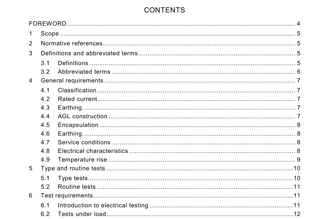
This standard specifies the characteristics of aeronautical ground lighting series transformers (AGLST) used in aeronautical ground lighting for 6,6 A series circuits, at a service voltage of up to 5 kV, supplied by constant current regulators up to 30 kVA in rating. AGL series transformers provide power to airport lighting luminaires or other loads (resistive) from their secondary circuits. The AGL series transformers provide continuity of the series circuit in the event of a loss of the load on the transformer, and electrical isolation between the primary circuit supplied by a constant current regulator, and the secondary circuit connected to the load under conditions defined in this standard. An AGL series transformer is be able to withstand a permanent short or open-circuit secondary series circuit. Specifications for similar series transformers intended for any primary or secondary currents other than 6,6 A, or to supply alternative voltages, constant power, reactive loads, etc., are not included in this standard.
4 General requirements
4.1 Classification There are seven types of AGL series transformers specified in this standard, defined by their nominal power, namely 30 W, 45 W, 65 W, 100 W, 150 W, 200 W and 300 W. See Table 1 for the required characteristics. 4.2 Rated current The rated primary and secondary currents shall be 6,6 A. 4.3 Earthing AGL series transformers may be provided with or without an earthing connection. 4.4 AGL construction The AGL series transformers shall have two electrically and physically separate windings, one primary and one secondary, wound on a magnetic core. The polarity of the windings shall be such that the primary plug corresponds to the large socket of the secondary receptacle. All internal electrical connections shall be permanent, e.g. by compression high-pressure crimping, high-temperature soldering, welding, etc. The shapes of the transformers are optional provided they meet all the requirements of this standard. Sharp edges shall be avoided. The AGL series transformer including all connector leads shall be able to be inserted through the open end of a cylinder 20 cm in diameter by 25 cm long, and shall easily and totally fit inside such a cylinder.The transformers shall be designed so that they may be installed and will perform to the requirements of this standard in any orientation. The AGL series transformers shall be provided with two single-conductor primary leads and a two-conductor secondary lead. 4.4.1 Primary connection leads The AGL series transformers shall be connected to the AGL primary series circuit cable by two insulated, multi-stranded, copper conductors, with at least a 6 mm 2 cross section, and a length measured from the transformer housing to the face of the connector of 60 10 0 + cm. The service voltage for the leads shall be 5 kV. One lead shall have a style 2 male plug at its end. The other lead shall have a style 9 female receptacle at its end. Unless otherwise agreed between the manufacturer and supplier, the connectors shall be provided with disposable shipping caps. 4.4.2 Secondary connection lead The secondary lead shall consist of two insulated, multi-stranded, copper conductors with an overall jacket, each core of minimum cross section 2,5 mm 2 , minimum service voltage 600 V, and a length measured from the transformer housing to the face of the connector of 120 10 0 + cm. The lead shall have a type 2, class A, style 7 or style 8 female receptacle at its end. Unless otherwise agreed between the manufacturer and supplier, the connector shall be provided with a disposable shipping cap.4.5 Encapsulation The AGL series transformer body, the connectors and the connection lead’s sheaths, shall be made of compatible materials. The case shall be composed of material formed directly on the core and coil assembly, or by compound filling a container. The transformer shall be permanently encapsulated without cracks, holes, or internal voids as far as practical. The encapsulation of the transformer must form a watertight casing, and must bond with its connection leads so as to provide a completely waterproof assembly. The encapsulation material shall have a durometer hardness IRHD (Shore A) of not less than 55 as measured in accordance with the test method of ISO 48. The minimum thickness of the encapsulation over the internal components shall be 6,5 mm at all points of the surface, for any type of encapsulant. The encapsulation materials shall be capable of withstanding acid and alkaline soils, as well as limited exposure to chemicals typically present on the aerodrome, including but not limited to oil, gasoline, and de-icing fluids. The encapsulating materials must resist limited UV exposure. These characteristics may be confirmed by testing material samples (only). The characteristics may be confirmed by tests sponsored by the transformer manufacturer, or by test results supplied by the materials manufacturer. These results may be applied to all AGL series transformers using the encapsulation material. If a transformer manufacturer uses more than one material for encapsulation, each such material shall meet these requirements.
