API RP 11AR pdf download
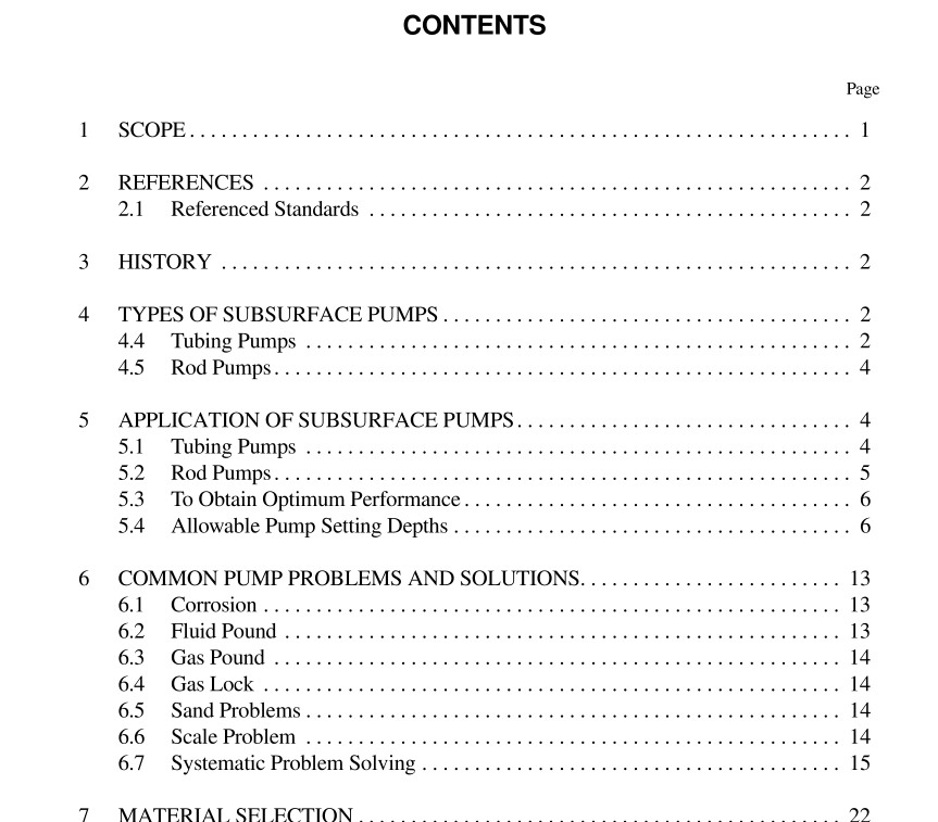
API RP 11AR pdf download.Recommended Practice for Care and Use of Subsurface Pumps
3 History
3.1 The first formal work toward development of API Std 11A was in 1924. In that year, a Committee on Standardiza- tion of Pumping Equipment and Engines was organized. The first issue of API Std 11A, Specification for Cold Drawn and Machined Working Barrels for Sucker Rod Pumps was dated May 1926. 3.2 In 1956, a subcommittee on subsurface pumps approved in principle a proposal that a task group be appointed to carry out the assignment of developing complete API standard pumps with interchangeability of parts and sim- plified part numbering system for pump assemblies and com- ponent parts. This charge was the beginning of API Spec 11AX and the demise of API Std 11A. 3.3 The first printing of API Spec 11AX was in January of 1961. At the 1966 Standardization Conference, the Commit- tee on Production Equipment agreed that a task group be appointed to revise the diagrams of typical pumps and incor- porate them into a separate RP, Recommended Practice of Care and Use of Subsurface Pumps . The work of this task group culminated in the First Edition of API RP 11AR being published in 1968.
4.5 ROD PUMPS
a. The rod pump is preferred over the tubing pump in the great majority of rod-pumped wells. The fact that the com- plete pump can be pulled with the sucker rod string without disturbing the tubing is the main reason for this preference. This reduces pulling unit time at the well by more than 50 percent over a tubing pump when both the barrel and plunger must be pulled. There are three types of rod pumps; the trav- eling-barrel, bottom-anchor (API RWT, or RHT), the stationary-barrel, bottom-anchor (API RWB, or RHB), and the stationary-barrel, top-anchor (API RWA, or RHA). b. When a rod pump has been selected, an API seating nipple is run on or near the bottom joint of tubing. Depending on well conditions or user preference, either the cup type or the mechanical bottom lock may be run if the pumps are bottom- anchor, or the cup type or mechanical top lock if the pumps are top-anchor. The complete rod pump with a seating assem- bly to match the seating nipple on the tubing string is run in on the sucker rod string. When the pump seats in the seating nipple, it is spaced as closely as possible to the bottom with pony rods. The final adjustment is made with the placement of the clamp on the polished rod. In gassy wells, it is desirable to keep the spacing very close, with the traveling assembly of the pump nearly touching at the bottom to minimize valve clearance at the bottom of the stroke. The principle of opera- tion of the rod pump is identical to that described for the tubing pump. The void created in the barrel by the upward motion of the plunger in stationary-barrel pumps permits the pump to be filled from the well bore. This fluid is then dis- placed into the rod tubing annulus on the subsequent downstroke.
5 Application of Subsurface Pumps
5.1 TUBING PUMPS (FIGURE 3) 5.1.1 Advantages a. A tubing pump provides the largest displacement possible in any size of tubing, just one quarter inch smaller than the nominal tubing I.D. Where the maximum displacement is needed, the tubing pump is the logical choice. b. A tubing pump is the strongest pump made. The heavy wall barrel is connected directly to the bottom of the tubing string with a collar, eliminating the need for a seating assem- bly on the pump to hold the pump in position. Also, the sucker rod string connects directly to the plunger top cage, eliminating the need for the valve rod required in stationary- barrel rod pumps. 5.1.2 Limitations a. The greatest disadvantage of the tubing pump is that the tubing string must be pulled in order to replace the pump bar- rel. This increases the pulling unit time at the well. b. The tubing pump is a poor installation in gassy fluid. Because of the length of the standing valve assembly and the puller on the plunger (and frequently the increased bore of an extension nipple) there is a large unswept area at the bottom of the stroke, causing a poor compression ratio. This reduces the effectiveness of the pump valving. It also causes low pump efficiency in wells where gas enters the pump suction along with the produced fluid. c. The increased bore of a tubing pump causes increased load on the rod string and pumping unit. It also increases stroke loss due to rod and tubing stretch.
