API TR 2567 pdf download
API TR 2567 pdf download.Evaporative Loss from Storage Tank Floating Roof Landings
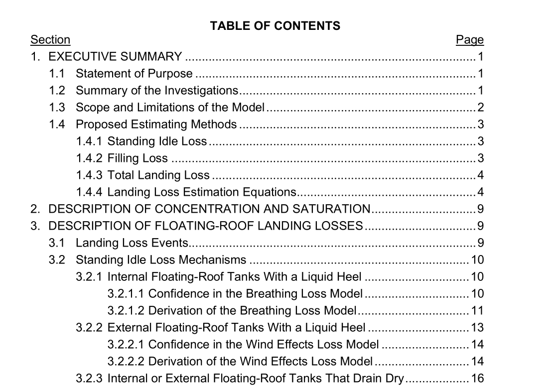
1.4.1 Standing Idle Loss.
The first two categories are described as having a liquid heel, which is a reference to stock liquid remaining in the bottom of the tank as it stands idle after having been emptied (see Figure 4). This heel of stock liquid provides a continuing source of vapors to replace those expelled by breathing (in the case of an internal floating-roof tank) or wind action (in the case of an external floating-roof tank). For each of these cases, then, standing idle loss is a process that is repeated on a daily basis. The third category is described as drain dry, which refers to a tank that is designed to drain its entire bottom to a sump (see Figure 5). The tank’s withdrawal line is located in the sump in a manner that leaves virtually no free-standing liquid in the tank after it has been emptied. The only stock liquid available for evaporation, then, is that which clings to the tank bottom and other wetted surfaces under the floating roof. Once this thin film has evaporated, there is no free stock liquid remaining to replenish vapors under the floating roof. Standing idle loss from a drain dry tank does not continue to occur day after day, but rather is limited to a one-time evaporation of the liquid clinging to the wetted surfaces. A tank only qualifies as a drain-dry tank if all of the free-standing liquid has been removed. If the tank drains to a sump, but a heel of free-standing liquid is left in the sump, then the tank would be considered to have a partial liquid heel. Flat bottom tanks that have most of the free-standing liquid removed by means of a vacuum truck typically have pools of liquid remaining, and should generally be considered to have a partial heel as well.
3.2 Standing Idle Loss Mechanisms
The loss mechanism assumed for standing idle loss in the 10/1/97 TGB Report was breathing of the vapor space under the floating roof. This mechanism involves the generation of vapors beneath the floating roof by evaporation of liquid remaining in the bottom of the tank, and the subsequent daily expulsion of a portion of these vapors in response to the daytime rise in ambient temperature. As the ambient temperature rises and heats the tank, the vapors expand and a portion of them are pushed out of the vapor space. The vapors that remain beneath the floating roof are eventually all expelled by incoming liquid when the tank is refilled. Although these vapors are generated while the tank is standing idle, they are included with the filling loss rather than the standing idle loss. After subsequent consideration, it was concluded that the breathing mechanism model applies only to internal floating-roof tanks with sufficient liquid remaining in the tank to continually replenish vapors lost by daily breathing (i.e., IFRTs with a liquid heel). The standing idle loss mechanism identified for external floating- roof tanks with a liquid heel is wind effects. When a liquid heel is not present because the tank has been drained virtually dry, then the standing idle loss mechanism appears to be the evaporation of the thin layer of liquid clinging to the bottom of the tank. This clingage mechanism applies to drain-dry operations for both internal and external floating-roof tanks.
3.2.1 Internal Floating-Roof Tanks With a Liquid Heel (full or partial).
Standing idle losses from a landed internal floating roof with a liquid heel are modeled as a breathing phenomenon. The vapor space beneath the internal floating roof is assumed to behave in a manner similar to the headspace of a fixed-roof tank. The height of the vapor space beneath the floating roof is substituted for the vapor space outage in the calculation method published in API’s Manual of Petroleum Measurement Standards, Chapter 19.1 3 (API MPMS 19.1), where this phenomenon is termed standing storage loss.
