API PUBL 4730 pdf download
API PUBL 4730 pdf download.Groundwater Remediation Strategies Tool
Estimation of mass flux across one or more transects through an affected groundwater plume involves the following principal steps:
1. Characterize Plume Concentrations: For each selected plume transect, sufficient groundwater sampling points must be available to define i) the full width and thickness of the plume and ii) the distribution of contaminant concentrations within the plume. Either single-level or multilevel groundwater monitoring points may be used for this purpose. Multilevel monitoring points can provide a more detailed three-dimensional characterization of contaminant concentrations in groundwater. However, single-level groundwater monitoring networks, while less accurate than multi-level networks, can still provide sufficient accuracy to support a mass flux analysis at many sites.(NOTE: an alternative method is to use the concentrations from contour lines as measurement points. The locations where the transect intersects contour lines from plume maps can be used to construct flow areas for the mass flux calculations). 2. Characterize Groundwater Flow: To characterize the specific discharge (q) across each plume transect, representative measurements are required for both the hydraulic flow gradient (i) and the hydraulic conductivity (K) of the flow system (where q = K x i). The groundwater flow direction and hydraulic gradient for each segment of a transect line can be determined from a potentiometric surface contour map based on static water level measurements of available sampling points. Representative measurements of the hydraulic conductivity of the groundwater-bearing unit should be obtained at one or more locations, using appropriate slug test or pumping test methods. 3. Select Plume Transects: To characterize mass flux, transects should be located at points where sufficient data are available to define affected groundwater concentrations and specific discharge, as defined in Steps 1 and 2 above. For two-dimensional data (i.e., from single-screen monitoring wells), the transect will represent a line extending across the full width of the plume, perpendicular to the direction of groundwater flow (see Figures 2 and 3). For uniform flow fields, this transect will be a straight line, but, for converging or diverging flowlines, the transect will be curvilinear in shape. For three-dimensional data (i.e., from multilevel monitoring wells), the transect line will represent a vertical plane through the groundwater plume, positioned perpendicular to groundwater flow (see Figures 4 and 5).4. Subdivide Transects Into Subareas: Each transect should be divided into subareas. Typically, each subarea represents a different concentration value. Two methods are commonly applied. For Method 1 , subareas are divided to represent the area between concentration isopleths on a contour map of the plume. The concentration is assumed to be the geometric mean of the two contour values. For Method 2, sufficient monitoring points are located directly on the transect to construct transect subareas. The dividing line between subareas is typically halfway between the measurement points. In some cases, a combination of Method 1 and Method 2 can be applied. For three-dimensional transects, the transect plume should be subdivided into polygons bounded by contour data (Method 1 ) or centered on available measuring points (Method 2) (See Figures 4 and 5 for an example of Method 2).
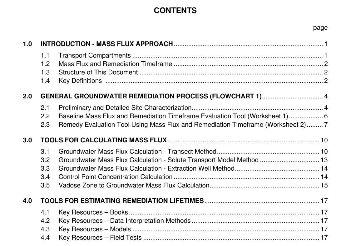
4.0 TOOL S FOR ESTIMATING REMEDIATION LIFETIMES
To estimate the source lifetime for use in soil and groundwater modeling, two general approaches can be used (Farhat et al, 2002): . Extrapolate concentration Vs. time trends. This can be done either for natural attenuation processes, or for a remediation system. However, several years of monitoring data are required to get a trend that is robust enough to be useful. ■ Use mass-based source models to estimate remediation timeframes. With a source mass estimate and the mass flux leaving the source, an estimate of the time required to achieve a remediation goal can be estimated. This is the only method that will provide information on the impact of proposed remediation measures (i.e., trend data before a remediation system is installed will not provide any information on the remediation timeframe of the system). Note that there is considerable uncertainty with estimating mass and remediation timeframes using this method, and that the final answers will likely be an order- of-magnitude endeavor. This section provides a list of references, resources, and tools for estimating remediation timeframes.
