API RP 11AR pdf download
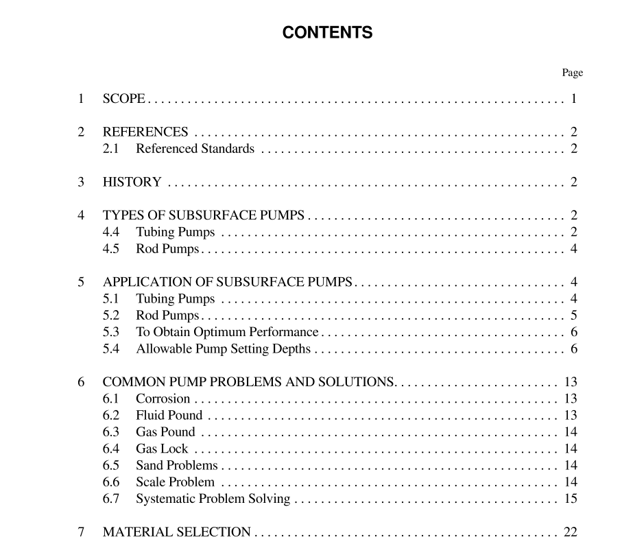
API RP 11AR pdf download.Recommended Practice for Care and Use of Subsurface Pumps
4.4 TUBING PUMPS (FIGURE 2)
a. The tubing pump is rugged in construction and simple in design. The barrel of a tubing pump is attached directly to the tubing string, usually at the bottom. Below the pump barrel is a seating nipple that receives and locks in place the standing value of the pump assembly. After this assembly has been run into the well and landed, the plunger assembly is run in on the sucker rod string. When the correct number of sucker rods and pony rods are run to allow the plunger assembly to fit into the pump barrel and seat the standing valve in the seating nip- ple, the plunger is ready for final spacing. b. The standing valve is run into the wall spacing to the bot- tom of the pump plunger by means of a standing valve puller. When the standing valve engages the seating nipple, it locks in place with either a mechanical lock or friction cups. The plunger may then be released from the standing valve by rotating the rod string counterclockwise. The plunger assem- bly is then raised to clear the standing valve on the bottom of the pump stroke, plus about a foot to compensate for rod overtravel. Final spacing is adjusted by the placement of the clamp on the polished rod. c. As the motion of the pumping unit causes the rods and the plunger to reciprocate, the pumping action begins. As the plunger starts the upstroke, the weight of fluid in the tubing causes the traveling valve to close. The upward motion of the plunger causes reduction of pressure in the pump barrel below the plunger and the pressure of fluid in the casing annulus then opens the standing valve, filing the void created by the upward movement of the plunger. d. As the plunger starts down, the standing valve closes. The pressure below the plunger builds up and opens the traveling valve. Thus the fluid that passed the standing valve on the upstroke, passes the traveling valve and through the hollow center of the plunger on the downstroke.
4.5 ROD PUMPS
a. The rod pump is preferred over the tubing pump in the great majority of rod-pumped wells. The fact that the com- plete pump can be pulled with the sucker rod string without disturbing the tubing is the main reason for this preference. This reduces pulling unit time at the well by more than 50 percent over a tubing pump when both the barrel and plunger must be pulled. There are three types of rod pumps; the trav- eling-barrel, bottom-anchor (API RWT, or RHT), the stationary-barrel, bottom-anchor (API RWB, or RHB), and the stationary-barrel, top-anchor (API RWA, or RHA). b. When a rod pump has been selected, an API seating nipple is run on or near the bottom joint of tubing. Depending on well conditions or user preference, either the cup type or the mechanical bottom lock may be run if the pumps are bottom- anchor, or the cup type or mechanical top lock if the pumps are top-anchor. The complete rod pump with a seating assem- bly to match the seating nipple on the tubing string is run in on the sucker rod string. When the pump seats in the seating nipple, it is spaced as closely as possible to the bottom with pony rods. The final adjustment is made with the placement of the clamp on the polished rod. In gassy wells, it is desirable to keep the spacing very close, with the traveling assembly of the pump nearly touching at the bottom to minimize valve clearance at the bottom of the stroke. The principle of opera- tion of the rod pump is identical to that described for the tubing pump. The void created in the barrel by the upward motion of the plunger in stationary-barrel pumps permits the pump to be filled from the well bore. This fluid is then dis- placed into the rod tubing annulus on the subsequent downstroke.
5.1 TUBING PUMPS (FIGURE 3)
5.1.1 Advantages a. A tubing pump provides the largest displacement possible in any size of tubing, just one quarter inch smaller than the nominal tubing I.D. Where the maximum displacement is needed, the tubing pump is the logical choice. b. A tubing pump is the strongest pump made. The heavy wall barrel is connected directly to the bottom of the tubing string with a collar, eliminating the need for a seating assem- bly on the pump to hold the pump in position. Also, the sucker rod string connects directly to the plunger top cage, eliminating the need for the valve rod required in stationary- barrel rod pumps. 5.1.2 Limitations a. The greatest disadvantage of the tubing pump is that the tubing string must be pulled in order to replace the pump bar- rel. This increases the pulling unit time at the well. b. The tubing pump is a poor installation in gassy fluid. Because of the length of the standing valve assembly and the puller on the plunger (and frequently the increased bore of an extension nipple) there is a large unswept area at the bottom of the stroke, causing a poor compression ratio. This reduces the effectiveness of the pump valving. It also causes low pump efficiency in wells where gas enters the pump suction along with the produced fluid.
