API RP 13B-2 pdf download
API RP 13B-2 pdf download.Recommended Practice for Field Testing of Oil-based Drilling Fluids
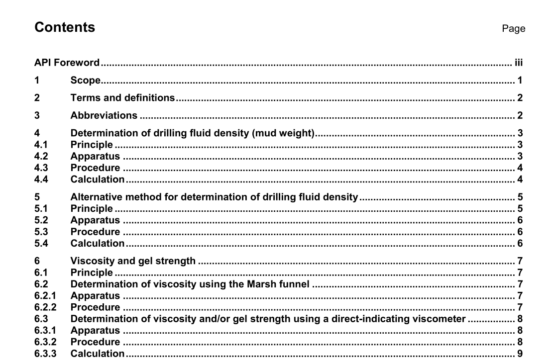
5.2 Apparatus
a) Any density-measuring instrument having an accuracy of ± 0,01 g/cm 3 , ± 10 kg/m 3 , ± 0,1 lb/gal, or ± 0,5 lb/ft 3 . The pressurized mud balance is the instrument generally used for density determinations of pressurized drilling fluids. The pressurized mud balance is designed such that the drilling-fluid holding cup and screw-on lid, at one end of the beam, is balanced by a fixed counterweight at the other end, with a sliding-weight rider free to move along a graduated scale. A level-bubble is mounted on the beam to allow for accurate balancing. Calibrate the instrument frequently with fresh water. Fresh water should give a reading of 1,0 g/cm 3 or 1 000 kg/m 3 at 21 °C (69,8 °F). If it does not, adjust the balancing screw or the amount of lead shot in the well at the end of the graduated arm as required. b) Thermometer, with a range of 0 °C to 105 °C (32 °F to 220 °F).
5.3 Procedure
5.3.1 Measure the temperature of the drilling fluid and record. 5.3.2 Fill the sample cup to a level slightly (approximately 6 mm) below the upper edge of the cup. 5.3.3 Place the lid on the cup with the attached check-valve in the down (open) position. Push the lid downward into the mouth of the cup until surface contact is made between the outer skirt of the lid and the upper edge of the cup. Any excess slurry will be expelled through the check-valve. When the lid has been placed on the cup, pull the check-valve up into the closed position, rinse off the cup and threads with water, and screw the threaded cap on the cup. 5.3.4 The pressurizing plunger is similar in operation to a syringe. Fill the plunger by submersing its end in the slurry with the piston rod completely inside. Then draw the piston rod upward, thereby filling the cylinder with slurry. This volume should be expelled with the plunger action and refilled with fresh slurry sample to ensure that this plunger volume is not diluted with liquid remaining from the last clean-up of the plunger mechanism. 5.3.5 Push the nose of the plunger onto the mating O-ring surface of the cap valve. Pressurize the sample cup by maintaining a downward force on the cylinder housing in order to hold the check-valve down (open) and at the same time to force the piston rod inside. A force of approximately 225 N (50 lbf) or greater should be maintained on the piston rod. 5.3.6 The check-valve in the lid is pressure-actuated; when the inside of the cup is pressurized, the check-valve is pushed upward into the closed position. To close the valve gradually ease up on the cylinder housing while maintaining pressure on the piston rod. When the check-valve closes, release pressure on the piston rod before disconnecting the plunger.5.3.7 The pressurized slurry sample is now ready for weighing. Rinse the exterior of the cup and wipe dry. Place instrument on the knife edge. Move the sliding weight right or left until the beam is balanced. The beam is balanced when the attached bubble is centred between the two black marks. Read the density from one of the four calibrated scales on the arrow side of the sliding weight. The density can be read directly in units of grams per cubic centimetre, pounds per gallon, and pounds per cubic foot, or as a drilling fluid gradient in pounds per square inch per 1 000 feet. 5.3.8 To release the pressure inside the cup, reconnect the empty plunger assembly and push downward on the cylinder housing. 5.3.9 Clean the cup and rinse thoroughly with base oil.
6 Viscosity and gel strength
6.1 Principle Viscosity and gel strength are measurements that relate to the flow properties (rheology) of drilling fluids. The following instruments are used to measure viscosity and/or gel strength of drilling fluids: a) Marsh funnel — a simple device for indicating viscosity on a routine basis; b) direct-indicating viscometer — a mechanical device for measurement of viscosity at varying shear rates. NOTE Information on the rheology of drilling fluids can be found in API RP 13D. 6.2 Determination of viscosity using the Marsh funnel 6.2.1 Apparatus a) Marsh funnel, calibrated to deliver 946 cm 3 (1 quart) of fresh water at a temperature of 21 ± 3 °C (70 ± 5 °F) in 26 ± 0,5 s, with a graduated cup as a receiver. The Marsh funnel shall have the following characteristics: 1) funnel cone, length 305 mm (12,0 in), diameter 152 mm (6,0 in) and a capacity to bottom of screen of 1 500 cm 3 (1,6 quarts); 2) orifice, length 50,8 mm (2,0 in) and inside diameter 4,7 mm (0,185 in); 3) screen, with 1,6 mm (0,063 in) openings (12 mesh); fixed at 19,0 mm (0,748 in) below top of funnel. b) Graduated cup, with capacity at least 946 cm 3 (1 quart). c) Stopwatch. d) Thermometer, with a range of 0 °C to 105 °C (32 °F to 220 °F).
