API RP 520-2 pdf download
API RP 520-2 pdf download.Sizing, Selection, and Installation of Pressure-relieving Devices in ReÞneries Part II-Installation
1 Scope
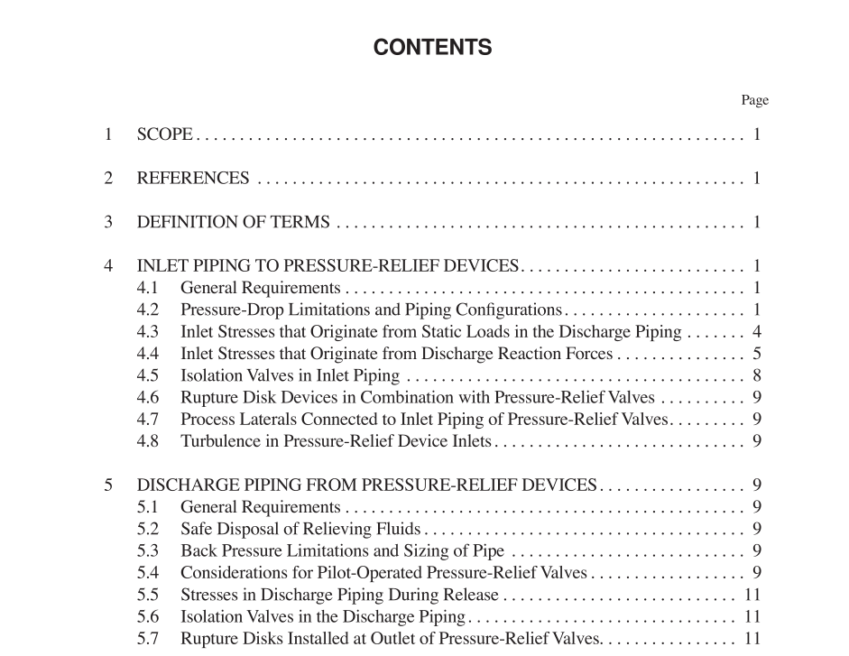
This recommended practice covers methods of installation for pressure-relief devices for equipment that has a maximum allowable working pressure (MAWP) of 15 psig (1.03 bar g or 103 kPA) or greater. Pressure-relief valves or rupture disks may be used independently or in combination with each other to provide the required protection against excessive pressure accumulation. As used in this recommended practice, the term pressure-relief valve includes safety relief valves used in either compressible or incompressible ßuid service, and relief valves used in incompressible ßuid service. This recom- mended practice covers gas, vapor, steam, two-phase and incompressible ßuid service; it does not cover special appli- cations that require unusual installation considerations.
4 Inlet Piping to Pressure-Relief Devices
4.1 GENERAL REQUIREMENTS For general requirements for inlet piping, see Figures 1 through 3.4.1.1 Flow and Stress Considerations Inlet piping to the pressure-relief devices should provide for proper system performance. This requires design consid- eration of the ßow-induced pressure drop in the inlet piping. Excessive pressure losses in the piping system between the protected vessel and a pressure-relief device will adversely affect the system-relieving capacity and can cause valve instability. In addition, the effect of stresses derived from both pressure-relief device operation and externally applied loads must be considered. For more complete piping design guide- lines, see ASME B31.3. 4.1.2 Vibration Considerations Most vibrations that occur in inlet piping systems are ran- dom and complex. These vibrations may cause leakage at the seat of a pressure-relief valve, premature opening, or prema- ture fatigue failure of certain valve parts, inlet and outlet pip- ing, or both. Vibration in inlet piping to a rupture disk may adversely affect the burst pressure and life of the rupture disk. Detrimental effects of vibrations on the pressure-relief device can be reduced by minimizing the cause of vibrations, by additional piping support, by use of either pilot-operated relief valves or soft-seated pressure-relief valves, or by pro- viding greater pressure differentials between the operating pressure and the set pressure. 4.2 PRESSURE-DROP LIMITATIONS AND PIPING CONFIGURATIONS For pressure-drop limitations and piping conÞgurations, see Figures 1, 2, 4, and 5. 4.2.1 Pressure Loss at the Pressure-Relief Valve Inlet Excessive pressure loss at the inlet of a pressure-relief valve can cause rapid opening and closing of the valve, or chattering. Chattering will result in lowered capacity and damage to the seating surfaces. The pressure loss that affects valve performance is caused by non-recoverable entrance losses (turbulent dissipation) and by friction within the inlet piping to the pressure-relief valve. When a pressure-relief valve is installed on a process line, the 3 percent limit should be applied to the sum of the loss in the normally non-ßowing pressure-relief valve inlet pipe and the incremental pressure loss in the process line caused by the ßow through the pressure-relief valve. The pressure loss should be calculated using the rated capacity of the pressure-relief valve. Pressure losses can be reduced by rounding the entrance to the inlet piping, by reducing the inlet line length, or by enlarg- ing the inlet piping. The nominal size of the inlet piping must be the same as or larger than the nominal size of the pressure- relief valve inlet connection as shown in Figures 1 through 3. Keeping the pressure loss below 3 percent becomes progres- sively more difÞcult at low pressures as the oriÞce size of a pressure-relief valve increases. An engineering analysis of the valve performance at higher inlet losses may permit increas- ing the allowable pressure loss above 3 percent. When a rup- ture disk device is used in combination with a pressure-relief valve, the pressure-drop calculation must include the addi- tional pressure drop developed by the disk (see 4.6 for addi- tional information on rupture disk devices).
