API RP 53 pdf download
API RP 53 pdf download.Recommended Practices for Blowout Prevention Equipment Systems for Drilling Wells
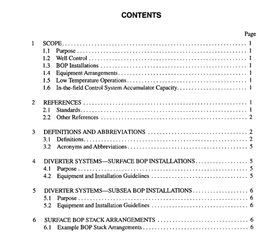
1 Scope
1.1 PURPOSE
The purpose of these recommended practices is to provide information that can serve as a guide for installation and test- ing of blowout prevention equipment systems on land and marine drilling rigs (barge, platform, bottom-supported, and floating). Blowout prevention equipment systems are com- posed of all systems required to operate the blowout preven- ters (BOPs) under varying rig and well conditions. These systems are: blowout preventers (BOPs), choke and kill lines, choke manifold, hydraulic control system, marine riser, and auxiliary equipment. The primary functions of these systems are to confine well fluids to the wellbore, provide means to add fluid to the wellbore, and allow controlled volumes to be withdrawn from the wellbore. In addition, diverter systems are addressed in this Recommended Practice, though their primary purpose is to safely divert flow rather than to confine fluids to the wellbore. Refer to API Recommended Practice 64 for additional information on diverter systems. Marine ris- ers are not dealt with in detail in this document. Refer to API Recommended Practice 16Q for additional information on marine drilling risers.
1.6 IN-THE-FIELD CONTROL SYSTEM ACCUMULATOR CAPACITY
It is important to distinguish between the standards for in- the-field control system accumulator capacity established here in Recommended Practice 53 and the design standards established in API Specification 16D. API Specification 16D provides sizing guidelines for designers and manufacturers of control systems. In the fac- tory, it is not possible to exactly simulate the volumetric demands of the control system piping, hoses, fittings, valves, BOPs, etc. On the rig, efficiency losses in the operation of fluid functions result from causes such as friction, hose expansion, control valve interflow as well as heat energy losses. Therefore, the establishment by the manufacturer of the design accumulator capacity provides a safety factor. This safety factor is a margin of additional fluid capacity which is not actually intended to be usable to operate well control functions on the rig. For this reason, the control system design accumulator capacity formulas established in Specification 16D are differ- ent from the demonstrable capacity guidelines provided here in Recommended Practice 53. The original control system manufacturer shall be con- sulted in the event that the field calculations or field testing should indicate insufficient capacity or in the event that the volumetric requirements of equipment being controlled are changed, such as by the modification or changeout of the BOP stack.
3 Definitions and Abbreviations
3.1 DEFINITIONS
The following definitions are provided to help clarify and explain use of certain terms in the context of this publication. Users should recognize that some of these terms can be used in othèr instances where the application or meaning may vary from the specific information provided in this publication. 3.1.1 accumulator: A pressure vessel charged with nitro- gen gas and used to store hydraulic fluid under pressure for operation of blowout preventers (BOPS). 3.1.2 annular preventer: A device that can seal around any object in the wellbore or upon itself. Compression of a reinforced elastomer packing element by hydraulic pressure effects the seal. 3.1.3 articulated line: An articulated line is a choke or kill line assembled as a unit, with rigid pipe, swivel joints, and end connections, designed to accommodate specified rel- ative movement between end terminations. 3.1.4 bell nipple (mud riser, flow nipple): A piece of pipe, with inside diameter equal to or greater than the blow- out preventer bore, connected to the top of the blowout pre- venter or marine riser with a side outlet to direct the drilling fluid returns to the shale shaker or pit. This pipe usually has a second side outlet for the fill-up line connection. 3.1.5 blind rams (blank, master): Rams whose ends are not intended to seal against any drill pipe or casing. The rams seal against each other to effectively close the hole. 3.1.6 blindshear rams: Blind rams with a built-in cut- ting edge that will shear tubulars that may be in the hole, thus allowing the blind rams to seal the hole. Used primarily in subsea BOP systems.
