API Spec 15LR pdf download
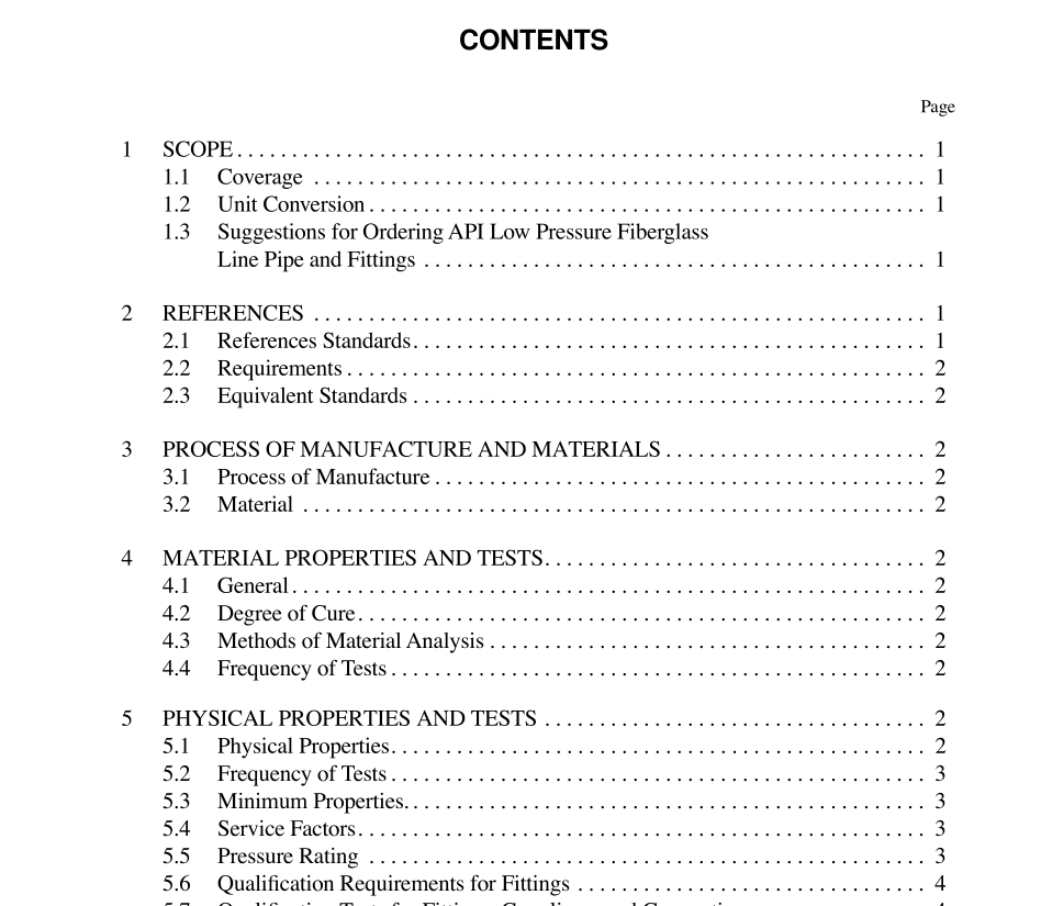
API Spec 15LR pdf download.Specification for Low Pressure Fiberglass Line Pipe and Fittings
1 Scope
1.1 COVERAGE This speciÞcation covers Þlament wound (FW) and centrif- ugally cast (CC) Þberglass line pipe and Þttings for pipe in diameters up to and including 24 in. in diameter and up to and including 1000 psig cyclic operating pressures. In addition, at the manufacturerÕs option, the pipe may also be rated for static operating pressures up to 1000 psig. It is recommended that the pipe and Þttings be purchased by cyclic pressure rat- ing. The standard pressure ratings range from 150 psig to 300 psig in 50 psig increments, and from 300 psig to 1000 psig in 100 psig increments, based on either cyclic pressure (ref. 5.5.1) or static pressure (ref. 5.5.2). Quality control tests, hydrostatic mill tests, dimensions, weights, material proper- ties, physical properties, and minimum performance require- ments are included. 1.2 UNIT CONVERSION A decimal/inch system is the standard for the dimensions shown in this speciÞcation. Nominal sizes will continue to be shown as fractions. For the purposes of this speciÞcation, the fractions and their decimal equivalents are equal and inter- changeable. Metric conversions are described in Appendix G.
3 Process of Manufacture and Materials
3.1 PROCESS OF MANUFACTURE Pipe furnished to this speciÞcation shall be produced by the centrifugal casting (CC) or Þlament winding (FW) methods. 3.2 MATERIAL The reinforced wall of pipe and Þttings shall consist of thermosetting polymers reinforced with glass Þbers. Accept- able polymers are epoxy resins, polyester resins, and vinyl ester resins. Couplings, connections, Þttings, and adhesives shall meet the performance properties listed in 5.6 and 5.7 and shall be manufactured by a process and from materials compatible with the pipe system. They shall at least be equally resistant to the same ßuids and environments as the pipe. Note: (1) Other resins and reinforcements shall be considered for inclusion in this standard when evidence is presented to show that they are suitable for the applications covered by this standard.
4 Material Properties and Tests
4.1 GENERAL Pipe and Þttings furnished to this speciÞcation shall con- form to the material requirements listed in 3.2. 4.2 DEGREE OF CURE Degree of cure shall be determined by differential scanning calorimetry (DSC) according to Appendix B at a minimum frequency of once per shift for each resin system used at each manufacturerÕs facility. DSC tests, in accordance with Appen- dix B shall also be conducted on Þttings at a frequency of one per 100 units of each size, type or pressure rating. The Tg shall not be more than 5¡C below the minimum values mea- sured in 5.2.2.1 and 5.7.4. Manufacturers shall establish these values for each resin system used. 4.3 METHODS OF MATERIAL ANALYSIS a. Degree of cure (Tg) shall be determined following the pro- cedure in Appendix B. b. Glass-resin ratios shall be determined following the proce- dures of Appendix A. 4.4 FREQUENCY OF TESTS The manufacturer shall supply a report showing the degree of cure (Tg) per 4.2 and 4.3 at the frequency required by 6.1.4 for pipe. Samples for material analysis shall be taken from production runs.
5 Physical Properties and Tests
5.1 PHYSICAL PROPERTIES Pipe furnished to this speciÞcation shall conform to physi- cal property requirements in 5.3. Certain other properties do not have speciÞed requirements but are nevertheless impor- tant in piping system design. The manufacturer shall perform the tests shown in 5.1a-5.1h as well as prepare all test reports in compliance with the applicable ASTM standard. These results shall be available upon request.
