API Spec 16D pdf download
API Spec 16D pdf download.Specification for Control Systems for Drilling Well Control Equipment and Control Systems for Diverter Equipment
1 Scope
1.1 GENERAL
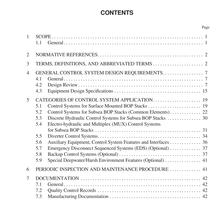
These specifications establish design standards for systems, that are used to control blowout preventers (BOPs) and associated valves that control well pressure during drilling operations. The design standards applicable to subsystems and components do not include material selection and manufacturing process details but may serve as an aid to purchasing. Although diverters are not considered well control devices, their controls are often incorporated as part of the BOP control system. Thus, control systems for diverter equipment are included herein. Control systems for drilling well control equipment typically employ stored energy in the form of pressurized hydraulic fluid (power fluid) to operate (open and close) the BOP stack components. Each operation of a BOP or other well component is referred to as a control function. The control system equipment and circuitry vary generally in accor- dance with the application and environment. The specifications provided herein describe the following control system categories: a. Control systems for surface mounted BOP stacks. These systems are typically simple return-to-reservoir hydraulic control systems consisting of a reservoir for storing hydraulic fluid, pump equipment for pressurizing the hydraulic fluid, accumulator banks for storing power fluid and manifolding, piping and control valves for transmission of control fluid to the BOP stack functions. b. Control systems for subsea BOP stacks (common elements). Remote control of a seafloor BOP stack requires specialized equipment. Some of the control system elements are common to virtually all subsea control systems, regardless of the means used for function signal transmission.c. Discrete hydraulic control systems for subsea BOP stacks. In addition to the equipment required for surface-mounted BOP stacks, discrete hydraulic subsea control systems use umbilical hose bundles for transmission of hydraulic pilot signals subsea. Also used are dual subsea control pods mounted on the LMRP (lower marine riser package), and housing pilot operated control valves for directing power fluid to the BOP stack functions. Spent water-based hydraulic fluid is usually vented subsea. Hose reels are used for storage and deployment of the umbilical hose bundles. The use of dual subsea pods and umbilicals affords backup security. d. Electro-hydraulic/multiplex control systems for subsea BOP stacks. For deepwater operations, transmission subsea of electric/ optical (rather than hydraulic) signals affords short response times. Electro-hydraulic systems employ multi-conductor cables, having a pair of wires dedicated to each function to operate subsea solenoid valves which send hydraulic pilot signals to the control valves that operate the BOP stack functions. Multiplex control systems employ serialized communications with multi- ple commands being transmitted over individual conductor wires or fibers. Electronic/optical data processing and transmission are used to provide the security of codifying and confirming functional command signals so that a stray signal, cross talk or a short circuit should not execute a function. e. Control systems for diverter equipment. Direct hydraulic controls are commonly used for operation of the surface mounted diverter unit. Associated valves may be hydraulically or pneumatically operated. f. Auxiliary equipment control systems and interfaces. For floating drilling operations, various auxiliary functions such as the telescopic joint packer, 30 in. latch/pin connection, riser annulus gas control equipment, etc., require operation by the control system. g. Emergency disconnect sequenced systems (EDS). (Optional) An EDS provides automatic LMRP disconnect when specific emergency conditions occur on a floating drilling vessel. These controls, though not specifically described herein, shall be sub- ject to the relevant specifications provided herein and requirements for similar equipment.
