AS 1603.17 pdf download
AS 1603.17 pdf download.Automatic fre detection and alarm systems
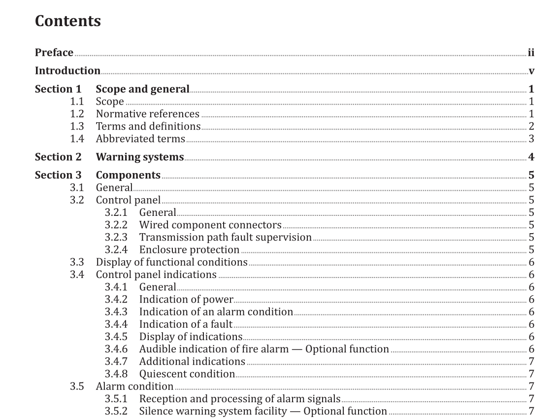
3.1 General
Components may be supplied in two ways: . [a) A standalone system containing the components, connections and instructions required for that installation; or (b) Individual components intended to be installed as part of another warning system. Components shall be compatible when interconnected to form a system. Leads connecting a component with the control panel shall be provided with a strain-relieving device. The lead shall be subjected to a pulling force of 20 N without jerks for 1 min in any direction allowed by the design. The pull shall not be transmitted to the joints between the leads and terminal connectors or between the leads and circuit board.
3.2 Control panel
3.2.1 General The control panel may be a standalone unit, conforming to this document, or it may be incorporated into the control and indicating equipment (CIE] as specified in either AS 1670.1 or AS 1670.4. The indications and controls shall be designed so that they are easily accessible. The control panel shall be able to function in the following conditions simultaneously: [i) Alarm condition. (i) Fault warning condition. All components, including flexible mains supply cord and cables, shall meet the relevant requirements of AS/ACIF S008, AS/NZS 60335.1 and AS/NZS 62368.1. 3.2.2 Wired component connectors Wired connections between system components shall be via mechanically latching connectors or screw terminals. Where mechanically latching connectors are used, it shall not be possible to make these connections incorrectly. 3.2.3 Transmission path fault supervision External transmission paths between the warning system components shall be supervised for faults that may prevent the transmission of an emergency warning signal. Where the transmission path is by means of physical connections [e.g. cabled), a transmission path fault shall be indicated at the control panel within 300 s. Where the transmission path is by means of wire-free connections, a transmission path fault shall be indicated at the control panel within 60 min. 3.2.4 Enclosure protection The enclosure ingress protection shall meet at least classification IP 21C as given in IEC 60529.
3.4 Control panel indications
3.4.1 General The control panel indicators shall meet the requirements of AS 7240.2:2018 Clause 4.11. 3.4.2 Indication of power The presence of power shall be indicated without prior manual intervention. This indication of power shall – – . (a) consist of a dedicated green light-emitting indicator or an alphanumeric display or both; and (b) meet the requirements of Clause 3.4.1. Components that are not powered by the control panel shall incorporate a power on indicator unless the provision of power is supervised by the control panel. 3.4.3 Indication of an alarm condition An alarm condition shall be visually indicated without prior manual intervention. This indication of an alarm condition shall – a consist of a dedicated red light-emitting indicator or an alphanumeric display or both; and (b) meet the requirements of Clause 3.4.1. NOTE This visual indicator is not the visual alarm device. The control panel shall respond to the alarm signal from an initiating device and activate the warning equipment within 15 s. 3.4.4 Indication of a fault A visual indication shall be given on the control panel of any of the fault conditions listed in Clause 3.6.2. The indication of a fault shall- consist of a general fault indicator or individual indicator(s) for each fault. The indicator shall consist of a yellow light- emitting indicator or alphanumeric display; and (b) meet the requirements of Clause 3.4.1. 3.4.5 Display of indications All required indications shall be clearly identifiable. 3.4.6 Audible indication of fire alarm一Optional function The audible indication may be the same for the alarm condition as for the fault warning condition. If they are different, the audible alarm indication shall have priority.
