AS 61466.1 pdf download
AS 61466.1 pdf download.Composite string insulator units for overhead lines with a nominal voltage greater than 1 000 V
1 Scope
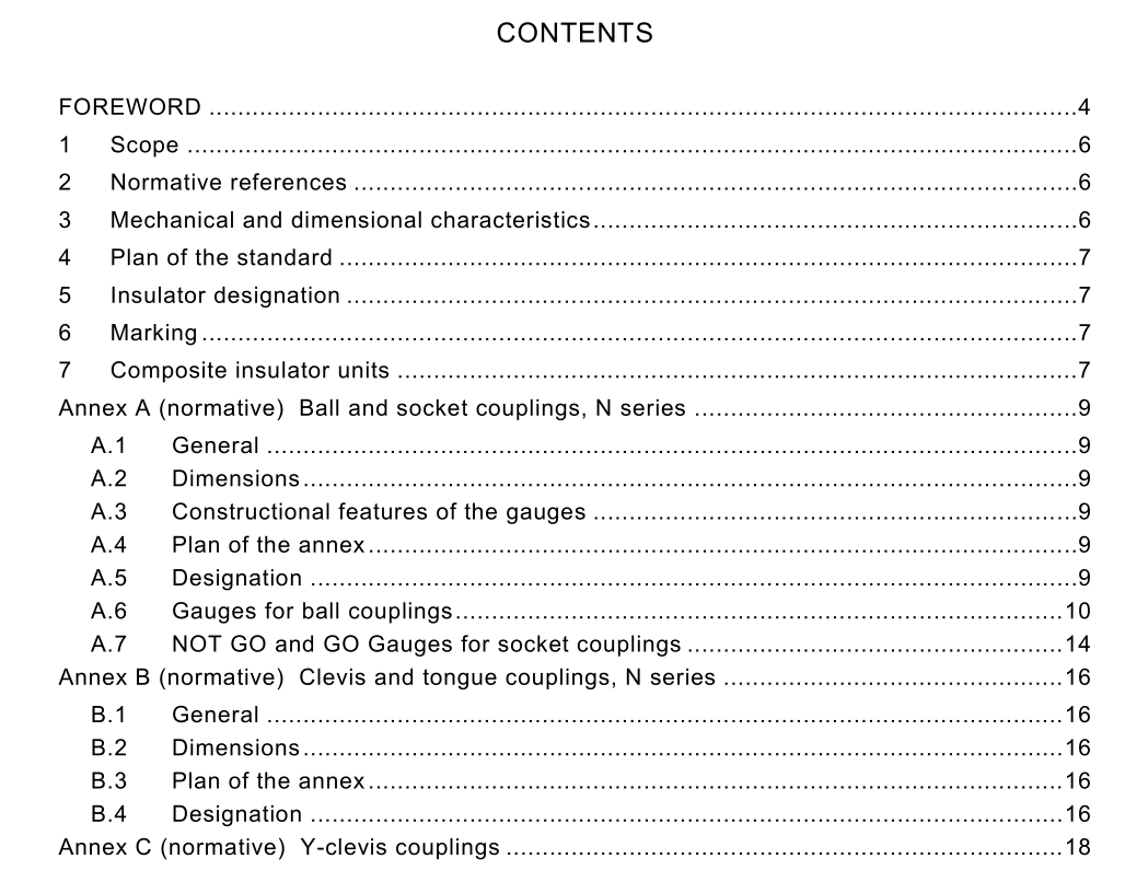
This part of IEC 61 466 is applicable to composite string insulator units for a.c. overhead lines with a nominal voltage greater than 1 000 V and a frequency not greater than 1 00 Hz. It also applies to insulators of similar design used in substations or on electric traction lines. This standard applies to string insulator units of composite type with ball, socket, tongue, clevis, Y-clevis or eye couplings, or a combination thereof. The object of this standard is to prescribe specified values for the mechanical characteristics of the composite string insulator units and define the main dimensions of the couplings to be used on the composite string insulator units in order to permit the assembly of insulators or fittings supplied by different manufacturers and to allow, whenever practical, interchangeability with existing installations. It also defines a standard designation system for composite string insulator units. NOTE 1 General definitions and methods of testing are given in IEC 61 1 09. NOTE 2 Only the dimensions necessary for assembly of the couplings are dealt with in this International Standard. Properties of material and working loads are not specified. The coordination of dimensions of the end- fittings with the strength classes is specified in Clause 7.
5 Insulator designation
Insulators are designated in Table 1 by letter CS followed by a number indicating the specified mechanical load (SML) in kilonewtons. The letter B, S, T, C, Y or E or a combination thereof which follows specifies a ball, socket, tongue, clevis, Y-clevis or eye coupling, see Figure 1 . The following figures specify the size of the coupling. When a combination of couplings are used, the first letter shall always express the coupling on the upper end of the insulator. The upper end of the insulator is defined in relation to the slope of the sheds. In the case of symmetrical profile of the sheds any order of the letters is acceptable. As examples, possible designations could be: CS 1 20 S/B1 6 indicates a composite insulator having a SML equal to 1 20 kN, a socket coupling according to IEC 601 20, size 1 6, at the upper end and a ball coupling according to IEC 601 20, size 1 6, at the other end. CS 1 20 C/T1 9N indicates a composite insulator having a SML equal to 1 20 kN, a clevis coupling according to Annex B, size 1 9N, at the upper end and a tongue coupling according to Annex B, size 1 9N, at the other end. Fittings of the same series conforming to different standards (e.g. IEC 601 20 and Annex A of this part of IEC 61 466) should be avoided on the same insulator.
The dimensions for the ball and socket couplings are expressed by dimensions for the GO and NOT GO gauges (see Figures A.1 to A.7). All dimensions indicated in Tables A.1 to A.6 are given in millimetres and refer to the finished product after surface treatment such as, for instance, hot dip galvanizing. The outside dimensions of the socket have not been fixed, since they depend on the mechanical characteristics of the material used. Only the dimensions necessary for assembly of the couplings are dealt with in this standard. In general, the ball is made of forged steel and the socket is made of malleable or ductile cast iron or forged steel. However, other materials may be used if they have mechanical characteristics corresponding to those given in Table 1 of this part of IEC 61 466. NOTE Dimensions are converted from inches.
