IEC 60068-3-5 pdf download
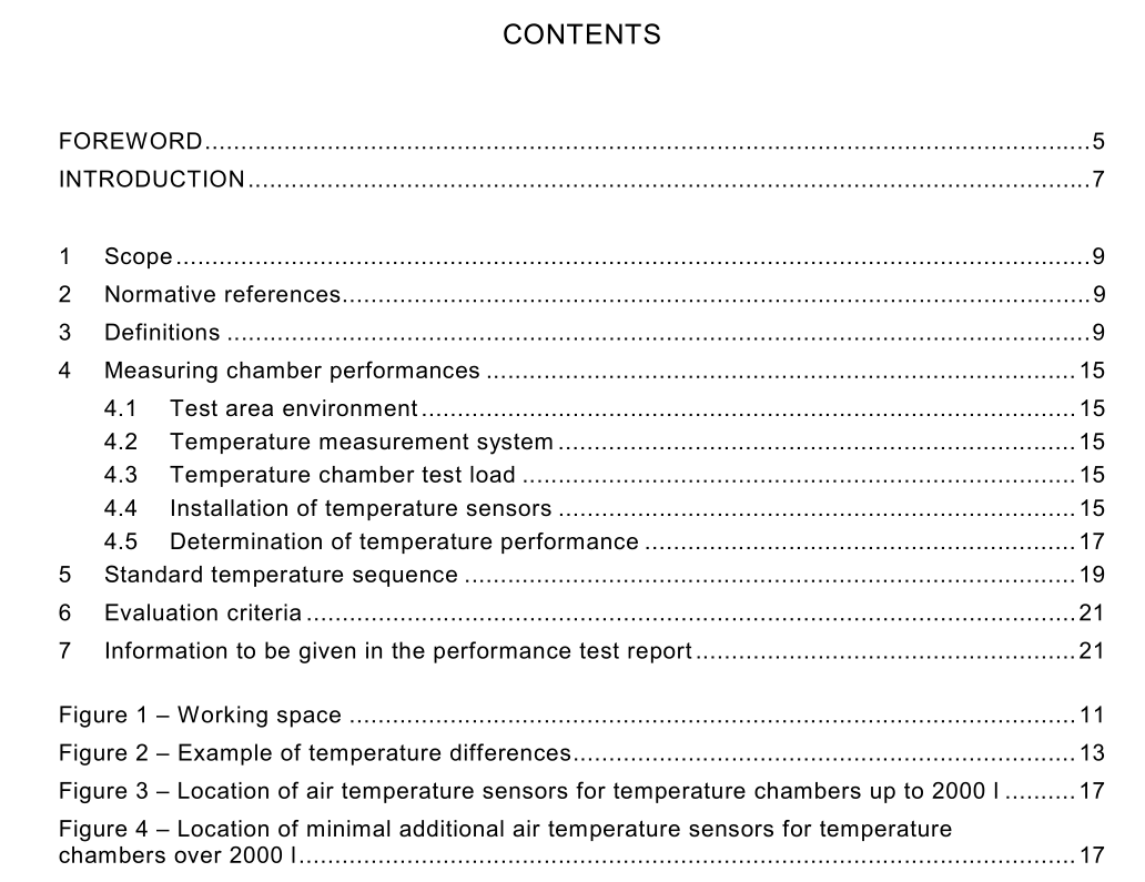
IEC 60068-3-5 pdf download.Supporting documentation and guidance – Confirmation of the performance of temperature chambers
1 Scope
This part of IEC 60068 provides a uniform and reproducible method of confirming that temperature test chambers, without load, conform to the requirements specified in climatic test procedures of IEC 60068-2 and other standards. This standard is intended for users when conducting regular chamber performance monitoring.
2 Normative references
The following referenced documents are indispensable for the application of this document. For dated references, only the edition cited applies. For undated references, the latest edition of the referenced document (including any amendments) applies. IEC 60068-1 , Environmental testing – Part 1: General and guidance IEC 60068-2 (all parts), Environmental testing – Part 2: Tests IEC 60068-3-6, Environmental testing – Part 3-6: Supporting documentation and guidance – Confirmation of the performance of temperature/humidity chambers IEC 60068-3-7, Environmental testing – Part 3-7: Supporting documentation and guidance – Measurements in temperature chambers for test A and test B (with load) IEC 60584-1 , Thermocouples – Part 1: Reference tables IEC 60751 , Industrial platinum resistance thermometer sensors ISO 1 001 2-1 , Quality assurance requirements for measuring equipment – Part 1: Metrological confirmation system for measuring equipment ISO 1 001 2-2, Quality assurance for measuring equipment – Part 2: Guidelines for control of measurement processes
3 Definitions
For the purpose of this part of IEC 60068, the following definitions apply. 3.1 temperature test chamber enclosure or space in some parts of which the temperature conditions, specified in IEC 60068-2, can be achieved 3.2 temperature setpoint desired temperature as set by the chamber controls 3.3 achieved temperature temperature in the chamber at any point within the working space after stabilization 3.4 temperature stabilization temperature at which all points in the working space have reached and maintained the setpoint temperature within a given tolerance 3.5 temperature fluctuation difference, after stabilization, between the maximum and minimum temperatures at any point in the working space during a specified interval of time 3.6 working space part of the chamber in which the specified conditions can be maintained within the specified tolerances3.7 temperature gradient maximum difference in mean value, after stabilization, at any moment in time between two separate points in the working space 3.8 temperature rate of change rate, in degrees per minute, for the transition between two specified temperatures measured at the centre of the working space 3.9 temperature variation in space difference in mean value, after stabilization, at any moment in time between the temperature at the centre of the working space and at any other point in the working space
4 Measuring chamber performances
4.1 Test area environment The environment around a temperature test chamber may influence the conditions inside the test chamber. The confirmation of performance of temperature chambers should be carried out under standard atmospheric conditions. The following items should be taken into consideration: – the ambient conditions described in IEC 60068-1 should be satisfied in principle; – the chamber should not be exposed to direct solar radiation; – the chamber should not be exposed to electromagnetic interference; – the chamber should be levelled; – the chamber should be fixed in a location free from any mechanical and acoustic vibration interference. Manufacturer’s advice on electrical power requirements and the environmental conditions should be taken into consideration. Abnormal conditions should be recorded. 4.2 Temperature measurement system The uncertainty of measurement of the output of the measurement system should be determined by calibration of the system, traceable to international standards (see ISO 1 001 2-1 and ISO 1 001 2-2). Normally sensors should be either the resistance type (in accordance with IEC 60751 ) or the thermocouple type (in accordance with IEC 60584-1 ). The 50 % response time in air of the sensor shall be between 1 0 s and 40 s. The response time of the overall system should be less than 40 s. In a temperature range from –200 °C to +200 °C the sensor measurement uncertainty should be in accordance with class A of IEC 60751 .
