IEC 60191-4 pdf download
IEC 60191-4 pdf download.Mechanical standardization of semiconductor devices
4 Coding system for semiconductor-device packages
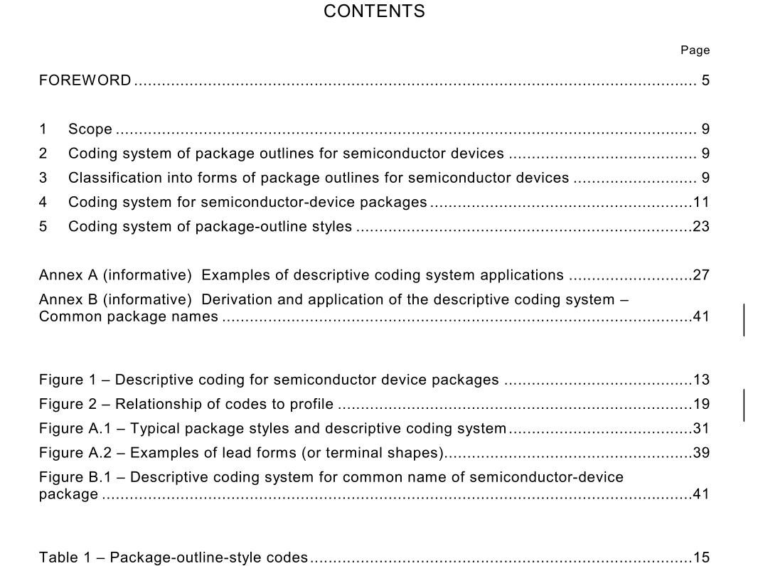
4.1 General The standard coding system is a method for identifying the physical features of an electronic device package family. The system is predicated upon a minimum two-character designator, which indicates the package outline style. This designator can be extended, through the use of optional, user-selected fields, to provide additional package information such as terminal position and count, terminal form, package shape, and predominant body material. 4.2 New descriptive codes If a new package that does not conform to one of the designated field character codes is being proposed, a new code may be recommended for standardization. 4.3 Descriptive designators The package outline style code is the only compulsory field within this descriptive designation system. Additional information may be provided using optional prefixes and suffixes described by the system. In general, these fields are independent of one another. Unless otherwise indicated herein, the users of this system may pick and choose which of these fields they wish to implement for their specific application (see figure 1). The descriptive designator may be extended with additional information, provided this information is separated from the descriptive designator by a slash (/) (see 4.3.6). 4.3.1 Minimum descriptive designator The minimum descriptive designator is a two-letter code that classifies device packages into standard package outline styles. These styles identify general external physical features. Common two-letter descriptive codes or abbreviations are included, such as CC, FP, SO, GA. Figure A.1 shows two-letter codes for various device package outline styles and depicts examples of each. Table 1 lists the two-letter package-outline-style codes described in clause 5.
4.3.2 Terminal-position prefix The two-letter, package-outline-style code may be supplemented with a single-letter prefix that identifies the physical terminal positions or, if applicable, the interconnect land pattern. Examples of three-letter designators include common acronyms or abbreviations, such as DIP, LCC (QCC preferred), PGA, QFP, SIP, ZIP. NOTE 1 A terminal is defined as an externally available point of connection. NOTE 2 The proper terminal-position prefix is determined by the interconnect land structure. For example, the code for a single row of terminals formed into a staggered configuration would be “Z”. Table 2 gives a list of one-letter, terminal-position prefix codes. 4.3.3 Package-body-material prefix The three-letter descriptive designator (see 4.3.2) may be further supplemented by a single- letter prefix that identifies the predominant package-body material. This prefix shall not be used unless the terminal-position prefix described in 4.3.2 is also used. Examples of such four- letter descriptive designators include common acronyms or abbreviations, such as CDIP, PDIP, PLCC (PQCC preferred), MELF, PQFP. Table 3 gives a list of one-letter package-body-material prefix codes. If the package-body material is other than one of those defined in table 3, the letter “X” shall be used within the descriptive designator to signify a special or new material and shall later be replaced with an IEC-approved code.4.3.4 Package-specific feature prefix Package-specific features may be described through the use of a multiletter prefix. The package-specific feature prefix shall be set off from the following portion of the descriptive designator by a dash (–). Table 4 gives a list of package-specific feature prefix codes. Figure 2 shows the relationship of codes to profile and pitch. 4.3.5 Lead-form and terminal-count suffixes The general lead form (or terminal shape) and/or the number of terminals on a package may be described through the use of two fields, the lead-form suffix and the terminal-count suffix. These two fields shall be set off from the preceding portion of the descriptive designator by a dash (–). Users of this system may choose to use the lead-form suffix, or the terminal-count suffix, or both. If the lead-form suffix is used in conjunction with the terminal-count suffix, it shall precede the terminal-count suffix.
