IEC 60191-6-3 pdf download
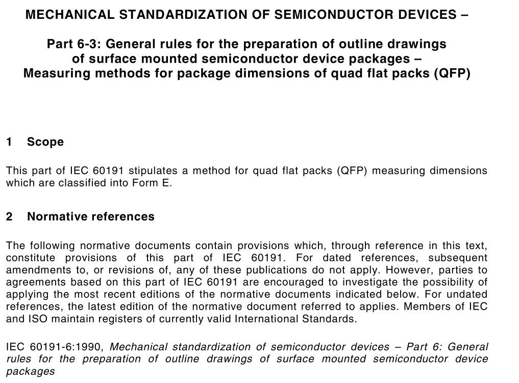
IEC 60191-6-3 pdf download.MECHANICAL STANDARDIZATION OF SEMICONDUCTOR DEVICES
1 Scope
This part of IEC 60191 stipulates a method for quad flat packs (QFP) measuring dimensions which are classified into Form E.
2 Normative references
The following normative documents contain provisions which, through reference in this text, constitute provisions of this part of IEC 60191. For dated references, subsequent amendments to, or revisions of, any of these publications do not apply. However, parties to agreements based on this part of IEC 60191 are encouraged to investigate the possibility of applying the most recent editions of the normative documents indicated below. For undated references, the latest edition of the normative document referred to applies. Members of IEC and ISO maintain registers of currently valid International Standards. IEC 60191-6:1990, Mechanical standardization of semiconductor devices – Part 6: General rules for the preparation of outline drawings of surface mounted semiconductor device packages 3 Definitions For the purpose of this part of IEC 60191, the definitions of IEC 60191-6 apply.
4 Measuring methods
4.1 The measuring methods described in this standard are for dimension values guaranteed to users on the basis of the following items. a) In general, measuring the dimensions shall be made with the semiconductor packages mounted on printed circuit-board as the guarantee is made to user. b) In general, measurement may be made either by hand or automatically. c) If a specified dimension is difficult to measure, the best alternative measuring method is defined as the formal measuring method. d) The dimensions that cannot be measured unless the package is destroyed may be calculated from other dimensions or replaced by representative values.Centres of opposite sides of a package, which are defined below, shall be connected together. An angle β subtended by the two crossing lines shall be obtained. A difference |90° – β| of the angle β from 90° shall be equally distributed to the sides to obtain rectangular axes. The rectangular axes are depicted as datum lines A and B of the package.4.4 Overall width H E / overall length H D / Package width D / package length E 4.4.1 Description a) As to the overall width and overall length, all lead tops should be located within the range t centring on the position which is at a theoretically correct distance of H E /2 or H D /2 from the datum A or B. b) As to the package width and length, the package end-face should be located within the range f centring on the position which is at a theoretically correct distance of E/2 or D/2 from the datum A or B.4.4.2 Measuring method a) HE/HD 1) Put the package on the surface plate to establish the datum reference S. 2) Make the datum A and B coincide with the measuring reference. 3) Find the logically precise distances HD/2 and HE/2 from the datum A and B. Then check if the tip of every lead on each package side is within the tolerance t (range) specified as the centre. b) E/D 1) Put the package on the surface plate to establish the datum reference S. 2) Make the datum A and B coincide with the measuring reference. 3) Find the theoretically precise distances D/2 and E/2 from the datum A and B. Then check if the package edge on each package side is within the tolerance f (range) specified as the centre. 4.5 Mounting height A 4.5.1 Description Let the height of a package from the seating plane to the top of the package be denoted as the mounting height. The mounting height therefore includes inclination and warping of the package.
