IEC 60404-14 pdf download
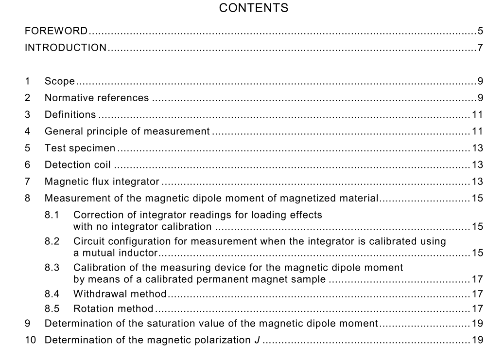
IEC 60404-14 pdf download.Methods of measurement of the magnetic dipole moment of a ferromagnetic material specimen by the withdrawal or rotation method
1 Scope
This part of IEC 60404 is applicable to all ferromagnetic materials. It is particularly aimed at the measurement of the magnetic dipole moment of permanent magnet (magnetically hard) materials and the measurement of the specific saturation magnetic polarization of cemented carbide materials having a ferromagnetic binder. The object of this part is to describe the general principles of the determination of the magnetic dipole moment of a ferromagnetic material specimen using a detection coil in an open magnetic circuit. By including a means of magnetizing the material to saturation, the saturation magnetic dipole moment can also be determined. In addition, the average magnetic polarization of a test specimen can be derived from the measurement of its magnetic dipole moment and volume. The calibration of magnetic moment coil systems and the measurement of the magnetic dipole moment of feebly magnetic materials can also be determined using this method. Measurements are normally performed at room temperature but measurements at other temperatures can be conducted by heating or cooling the volume occupied by the test specimen within the detection coil. The measurement of remanence, coercivity, maximum energy product and other parameters can be made in a closed magnetic circuit as described in IEC 60404-4 and IEC 60404-5. Measurement of the coercivity H cJ of soft and semi-hard materials can also be performed in an open circuit as described in IEC 60404-7.
5 Test specimen
The test specimen shall be in any convenient shape which can be accommodated within the uniform field region of the detection coil. If the saturation magnetic dipole moment is to be determined, a regular shaped test specimen of dimensions compatible with the magnetizing arrangement shall be used. Where materials are not magnetically isotropic, their magnetic axis shall be determined and marked on the appropriate surface of the test specimen, or in a drawing.
6 Detection coil
A calibrated detection coil shall be used. Its dimensions shall be such that the sensing region has a field uniformity of at least 1 % over the shape and volume equivalent to or greater than that of the test specimens to be measured. The magnetic field to current constant k h for the detection coil can be calibrated by passing current through the coils and measuring the current and the magnetic field strength at the centre with a calibrated magnetic field sensing device, for example a Hall probe, or it can be calibrated by an accredited laboratory. NOTE 1 For the measurement of the magnetic moment, the detection coil does not produce any magnetic field. In fact it is used as a search coil connected to a calibrated magnetic flux integrator. Nevertheless, the magnetic field to current constant for the coil is required in the calculation of the magnetic moment. NOTE 2 The most commonly used type of a detection coil is a pair of Helmholtz coils. Other appropriate coils or solenoidal systems can be used. Compensated coils which are insensitive to magnetic disturbances can also be applied.
7 Magnetic flux integrator
A magnetic flux integrator shall be used to determine the magnetic flux from the voltage induced due to the rotation or removal of the test specimen from the detection coil. The magnetic flux integrator shall be calibrated using the detection coil and the mutual inductor with its secondary winding in series (see figure 1), or it can be calibrated by an accredited laboratory.
