IEC 61378-2 pdf download
IEC 61378-2 pdf download.Convertor transformers
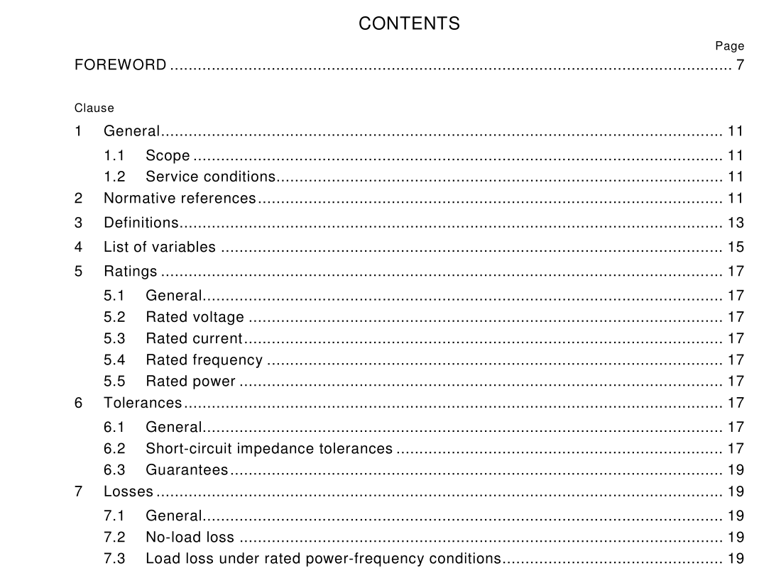
1 General
1.1 Scope This part of IEC 61378 applies to oil-immersed three-phase and single-phase convertor transformers for use in HVDC power transmission. It applies to transformers having two, three or multiple windings. This standard does not apply to – convertor transformers for industrial applications (see IEC 61378-1); – convertor transformers for traction applications (see IEC 60310). 1.2 Service conditions 1.2.1 General Convertor transformers in this standard shall comply with the service conditions stated in IEC 60076-1, except where it is clearly not applicable to convertor transformers or when other requirements are specified herein. It is assumed that the transformer operates in an approximately symmetrical three-phase system, unless otherwise stated. 1.2.2 Temperature If any part of the transformer (for example, the valve bushings) protrudes into the valve hall, the maximum temperature in the valve hall shall be specified in addition to the normal ambient temperature. 1.2.3 Load current The currents flowing through the transformers contain harmonics. Residual d.c. currents also flow through the valve windings. The supplier shall be provided with the harmonic content and the magnitude of the residual d.c. currents in the enquiry and have it confirmed during the contract stage. 1.2.4 Direction of power flow Unless otherwise specified, the transformer shall be designed for both rectifier and inverter operation.
3 Definitions
For the purpose of this part of IEC 61378, the definitions of IEC 60050 (IEV) apply. Additional definitions of more specific transformer and convertor terms are given in IEC 60076-1 and IEC 60146-1-1, respectively. Where some of these terms are at variance with earlier definitions of the same terms, found in the IEV, the terms specified in IEC 60076-1 and IEC 60146-1-1 will take precedence.
5 Ratings
5.1 General The rating characteristics of the transformer are expressed in steady-state sinusoidal quantities of current and voltages at rated fundamental frequency. The guaranteed losses, impedances and noise level shall correspond to these values. NOTE North American practice establishes nameplate rating in kVA based on both r.m.s. and fundamental frequency. 5.2 Rated voltage The rated voltage is the r.m.s. value of the fundamental component of the line-to-line voltage. 5.3 Rated current The rated current is the r.m.s. value of the fundamental component of the line current. 5.4 Rated frequency The rated frequency is the fundamental frequency of either 50 Hz or 60 Hz for which the transformer is designed. 5.5 Rated power The rated power is the product of the rated voltage and rated current, hence the rated three- phase power is as follows:
6 Tolerances
6.1 General The tolerances shall be in accordance with table 1 of IEC 60076-1, with the exceptions given in 6.2. 6.2 Short-circuit impedance tolerances The impedance at the principal tap shall not deviate by more than ±5 % of the guaranteed value. For transformers having a tapping range not exceeding 30 %, the impedance over the usual operating part of the range shall not exceed ±5 % of the value at the principal tapping and not more than ±10 % of the value at the principal tapping over all other parts of the range. The usual part of the tapping range shall be agreed between the supplier and the purchaser. The tolerances on impedance over the tapping range for transformers having a tapping range greater than 30 % shall be agreed between supplier and purchaser before contract.
7 Losses
7.1 General The total losses of a convertor transformer shall be the sum of the no-load loss and the load loss at rated values. The guaranteed losses shall be within the tolerances of table 1 of IEC 60076-1. 7.2 No-load loss No-load loss and no-load current are measured in the same way as for conventional a.c. transformers according to 10.5 of IEC 60076-1. This shall be the guaranteed no-load loss. NOTE The harmonic voltages and d.c. bias currents have an effect on no-load loss and no-load current. However, in practice the differences due to this effect can be disregarded in comparison to the total losses of the transformer. 7.3 Load loss under rated power-frequency conditions The load loss shall be measured in accordance with 10.4 of IEC 60076-1.
