IEC 61479 pdf download
IEC 61479 pdf download.Live working – Flexible conductor covers (line hoses) of insulating material
1 Scope
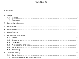
This International Standard is applicable to flexible insulating covers (line hoses) for the protection of workers from accidental contact with live or earthed electrical conductors and for the avoidance of short circuits during live working. 1.1 Classes Five classes of conductor covers, differing in electrical characteristics, are provided and designated as class 0, class 1, class 2, class 3, and class 4. 1.2 Categories Six categories of conductor covers differing in composition and properties are provided: category A – acid resistant, category H – oil resistant, category C – formulated for extreme low temperature environments, category W – formulated for extreme high temperature environ- ments, category Z – ozone resistant, and category P – formulated for humid environment. NOTE Types II and III material of ASTM D-1050 would be category Z. 1.3 Styles Various styles of conductor covers, differing in construction characteristics are available and six of these are designated as style A, style B, style C, style D, style E, (see figure 1), and style F.
3 Definitions
For the purpose of this International Standard, the following definitions apply. 3.1 protective cover rigid or flexible cover made of insulating material used to cover energized and/or dead parts and/or adjacent earthed (grounded) parts in order to prevent contact NOTE A protective cover is generally designed to provide a required insulation level which makes it able to provide protection only when a worker inadvertently comes into contact with the protective cover and for only a short duration. [IEV 651-04-01, modified] 3.2 conductor cover protective cover made of insulating material and used to shroud the conductor NOTE These covers can be either flexible or rigid. In general, they are commonly called “line hose” or “line guards”. [IEV 651-04-03] 3.3 elastomer generic term that includes rubber, latex and elastomeric compounds that may be natural or synthetic or a mixture or a combination of both 3.4 plastic material which contains as an essential ingredient a high polymer and which at some stage of its processing into finished products can be shaped by flow [ISO 472 modified] 3.5 proof test voltage the specified voltage that is applied to a device for the time defined under specific conditions to assure that the electrical strength of the insulation is above a specific value 3.6 flashover breakdown between electrodes in a gas or a liquid or in vacuum, at least partly along the surface of solid insulation [IEV 212-01-37] 3.7 puncture path produced through a solid by a breakdown producing permanent damage. The term is also used as a synonym for electrical breakdown in solids [IEV 212-01-38] 3.8 acceptance test contractual test to prove to the customer that the device meets certain conditions of its specification [IEV 151-04-20] 3.9 routine test test to which each device is subjected during or after manufacture to ascertain whether it complies with certain criteria [IEV 151-04-16] 3.10 sampling test test on a number of devices taken at random from a batch [IEV 151-04-17]
6 Physical requirements
6.1 Shape The shape of typical styles of conductor cover is indicated in figure 1 and designated by the following six styles with the following characteristics: – style A: straight style with an essentially constant cross-section throughout its length; – style B: connector-end style, similar to the straight style except that it shall have a moulded connector permanently affixed to one end; – style C: extended-lip style; – style D: extended-lip style with a moulded connector permanently affixed to one end; – style E: interlocking style; – style F: other shapes. Other styles may be used and should be shaped so as to restrict inadvertent access to energized parts or earthed parts. 6.2 Dimensions Recommended dimensions and tolerance are indicated in table 2.
