IEC 61514 pdf download
IEC 61514 pdf download.Industrial-process control systems – Methods of evaluating the performance of valve positioners with pneumatic outputs
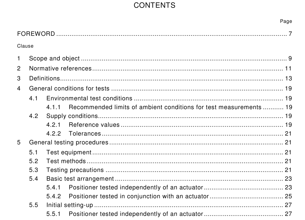
1 Scope and object
This International Standard specifies tests designed to determine the static and dynamic performance of single-acting or double-acting positioners. The tests may be applied to positioners which receive standard analogue input signals (as specified in IEC 60381 and IEC 60382) and have a pneumatic output. NOTE For positioners with pulsed or digital input signals, equivalent criteria may be applied. The methods described may not fully apply to positioners with digital controllers or positioners with pulsed outputs. Testing may be conducted either on a positioner alone, independently of an actuator, or on a positioner mounted and connected to a specific actuator, as a combined unit. The text makes clear where different approaches are required. The methods of evaluation given in this standard are intended for use by manufacturers to determine the performance of their products, and by users, or independent testing establish- ments, to verify manufacturers’ performance specifications. The closest liaison should be maintained between the evaluating body and the manufacturer. Note should be taken of the manufacturer’s specifications for the instrument when the test programme is being decided, and the manufacturer should be invited to comment on both the test programme and the results. His comments on the results should be included in any report produced by the testing organization.This standard is intended to provide definitions of positioner elements, actions, and characteristics, to specify uniform methods of measuring performance errors and effects of influence quantities on those characteristics, and to describe methods of reporting and evaluating the results of the measurement data obtained. The test conditions described in this publication (for example range of ambient temperatures and power supply) relate to conditions which commonly arise in use. Consequently, the values specified shall be used where no other values are specified by the manufacturer or user. If other values are used, they should be stated. It is recognized that the manufacturer’s specifications and instructions for installation and operation should apply during all steps. The tests specified in this standard are not necessarily sufficient for instruments specifically designed for unusually arduous conditions. Conversely, a reduced series of tests may serve adequately for instruments designed to perform within a more limited range of conditions. When a full evaluation, in accordance with this standard, is not required or possible, those tests which are required should be performed and the results reported in accordance with the relevant parts of this standard. In such cases, the test report should state that it does not cover the full number of tests specified herein.
3 Definitions
For the purpose of this standard, the definitions given in IEC 60902 and IEC 60050(1 61 ) shall be applied, in addition to the following definitions. 3.1 positioner position controller connected to the moving part of a final control element or its actuator; automatically adjusts its output signal Y to the actuator in order to maintain a desired travel signal X that bears a predetermined relationship to the input signal W NOTE In this standard, only positioners with pneumatic output signals Y are considered. The input signal W may be an air pressure (pneumatic positioner), or an electric current or voltage (electro-pneumatic positioner), or a pulse or digital signal. 3.1 .1 single-acting positioner positioner (see figure 1 a) having one output signal Y which acts on one side of the actuator. The returning force for the actuator is usually provided by springs 3.1 .2 double-acting positioner positioner (see figure 1 b) providing two output signals Y D and Y R connected to opposite sides of the actuator diaphragm or piston 3.2 input signal W reference input signal which represents the desired position of the associated control element 3.3 travel signal X signal which results from the linear or angular travel caused by movement of the final control element or its actuator 3.4 output signal Y air pressure delivered to the actuator of the final control element 3.5 supply pressure P s air pressure at the supply connector of the positioner 3.6 action action is direct when the output signal Y increases as the value of the input signal W increases. The action is reverse when the output signal Y decreases as the value of the input signal W increases 3.7 split ranging special adjustment in which the full travel of the actuator is achieved from only part of the whole input range (for example 0 % to 50 % or 50 % to 1 00 %)
