IEC 61952 pdf download
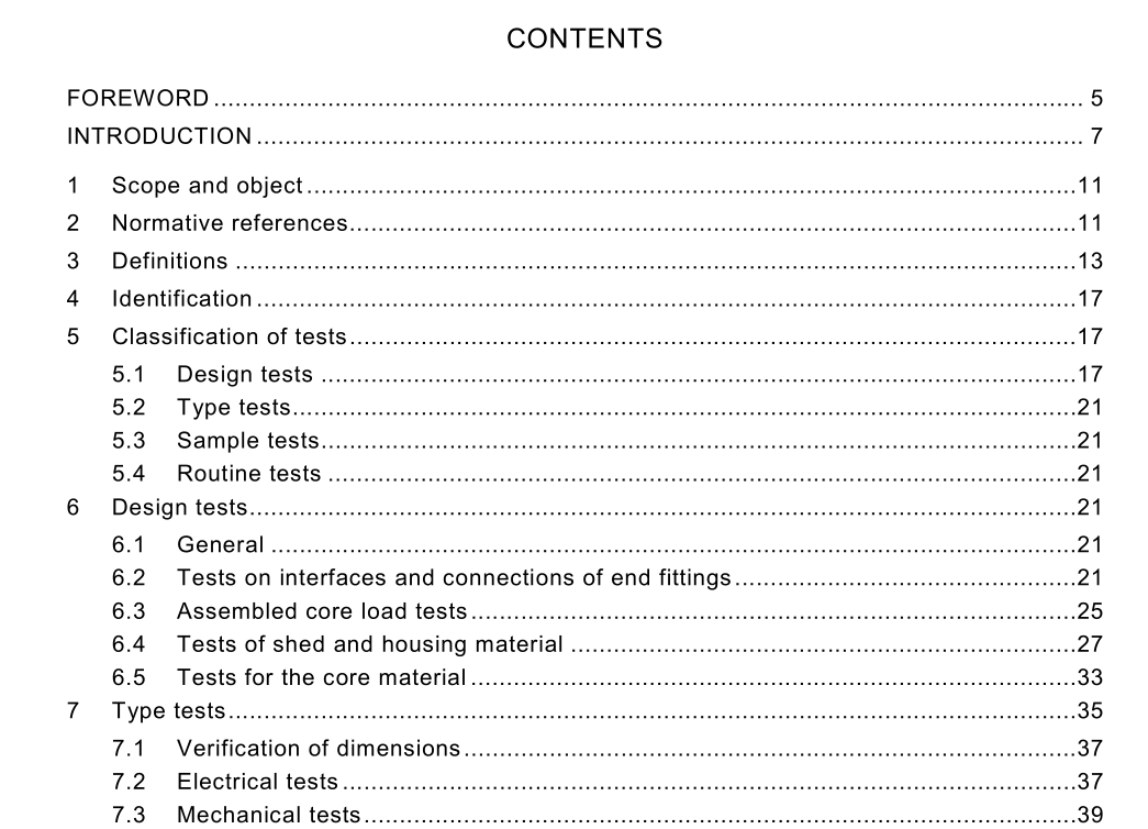
IEC 61952 pdf download.Insulators for overhead lines – Composite line post insulators for alternative current with a nominal voltage >1 000 V
1 Scope and object
This International Standard applies to composite line post insulators consisting of a load- bearing, cylindrical, insulating solid core made up of fibres – usually glass – in a resin-based matrix, a housing (outside the insulating core) made of elastomer material (e.g. silicone or ethylene-propylene) and end fittings permanently attached to the insulating core. Composite line post insulators covered by this standard are subjected to cantilever, tensile and compressive loads, when supporting the line conductors. They are intended for use on a.c. overhead lines with a rated voltage greater than 1 000 V and a frequency not greater than 100 Hz. The object of this standard is to – define the terms used, – prescribe test methods, – prescribe acceptance or failure criteria. This standard does not include requirements dealing with the choice of insulators for specific operating conditions.
3 Definitions
For the purposes of this International Standard, the following definitions apply. 3.1 composite line post insulator insulator consisting of a load-bearing cylindrical insulating solid core, a housing and end fittings attached to the insulating core. It is intended to be subjected to cantilever, tensile and compressive loads 3.2 core internal insulating part of a composite line post insulator designed to ensure the mechanical characteristics. The core usually consists of glass-fibres in a resin-based matrix 3.3 housing external insulating part of composite line post insulator providing necessary creepage distance and protecting core from environment. An intermediate sheath made of insulating material may be part of the housing 3.4 housing profile shape and dimensions of the housing which include the following: – shed overhang(s) – shed thickness at the base and at the tip – shed spacing – shed repetition – shed inclination(s).3.5 shed projecting part of the housing intended to increase the creepage distance 3.6 interface surface between different materials. Various interfaces occur in most composite line post insulators, e.g. – between glass fibres and impregnating resin, – between core and housing, – between various parts of the housing, e.g. between sheds or between sheds and sheath, – between housing, core and end fittings 3.7 end fittings of a composite line post insulator devices forming an integral and permanent part of the insulator intended to connect it to a supporting structure or to conductor hardware. The base end fitting of a composite line post insulator is where the maximum cantilever stress usually occurs. The line end fitting is where the cantilever load is usually applied 3.8 connection zone zone where the mechanical load is transmitted between the core and the end fitting 3.9 coupling zone part of the end fitting which transmits the load to the hardware external to the composite line post insulator 3.10 tracking irreversible degradation consisting of the formation of conductive paths starting and developing on the surface of an insulating material. These paths are conductive even under dry conditions. Tracking can occur on surfaces in contact with air and also on the interfaces between different insulating materials 3.11 erosion irreversible and non-conducting degradation of the surface of the insulator that occurs by loss of material. This can be uniform, localized or tree-shaped NOTE Light surface traces, commonly tree-shaped, can occur on composite line post insulators, as on ceramic insulators, after partial flashover. These traces are not considered to be objectionable as long as they are non- conducting. When they are conducting they are classed as tracking. 3.12 delamination of the core irreversible loss of bonding within fibre laminates perceivable by the naked eye 3.13 crack any internal fracture or surface fissure of depth greater than 0,1 mm
