IEC TS 62033 pdf download
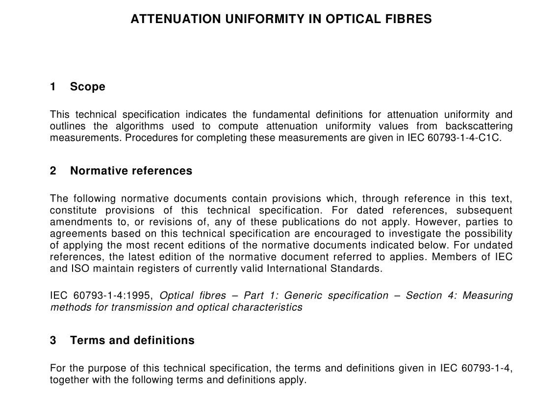
IEC TS 62033 pdf download.ATTENUATION UNIFORMITY IN OPTICAL FIBRES
1 Scope
This technical specification indicates the fundamental definitions for attenuation uniformity and outlines the algorithms used to compute attenuation uniformity values from backscattering measurements. Procedures for completing these measurements are given in IEC 60793-1 -4-C1 C.
2 Normative references
The following normative documents contain provisions which, through reference in this text, constitute provisions of this technical specification. For dated references, subsequent amendments to, or revisions of, any of these publications do not apply. However, parties to agreements based on this technical specification are encouraged to investigate the possibility of applying the most recent editions of the normative documents indicated below. For undated references, the latest edition of the normative document referred to applies. Members of IEC and ISO maintain registers of currently valid International Standards. IEC 60793-1 -4:1 995, Optical fibres – Part 1 : Generic specification – Section 4: Measuring methods for transmission and optical characteristics
3 Terms and definitions
For the purpose of this technical specification, the terms and definitions given in IEC 60793-1 -4, together with the following terms and definitions apply. 3.1 attenuation uniformity change in the attenuation coefficient over the length of an optical fibre or cable 3.2 optical time domain reflectometer (OTDR) trace plot of backscattered power (dB) vs. position within the fibre or cable, or the data from which the plot is derived 3.3 bi-directional backscattering technique completion of a backscattering measurement from each end of a fibre. A combination of the two traces (see equation 1 ) that yields accurate indications of attenuation for any section within the fibre or cable
7 Calculations
Attenuation uniformity is based on the bi-directional backscattering technique [1 ] * . The bi- directional backscatter trace is represented as a function, y ( z ), with y being the back-scattered power (in decibels) and z being the position (in kilometres). It is computed by reversing the position of each location of one of the uni-directional traces and computing the difference between the two uni-directional traces, divided by two, for each position. The bi-directional trace may be derived from multiple measurements or from appropriately filtered data having the same effect. The uniformity parameter, X A , is defined in terms of the sliding window (SW) algorithm in which the attenuation coefficient is evaluated across a fixed sub-length, L , (sliding window width) of the fibre, ideally sliding along the fibre, starting from each of a set of positions: z 1 , z 2 , … . The attenuation coefficient values at those positions can be represented as follows:lternatively, the fitted slope of the trace at the defined positions may be substituted for the values of A ( z i ; L ). The uniformity parameter is the difference between the maximum of the A ( z i , L ) values and the average attenuation coefficient of the whole fibre, given by its end-to-end attenuation coefficient, α ( λ ) as determined by any method in IEC 60793-1 -4:For a given fibre, the value of X A depends on the value of the sliding window length, L , and the distance between the positions z i . Alternatively, the generalized sliding window (GSW) algorithm (see [2] and [3]) will provide coefficients, α r , and ε r , such that for a defined range of L
